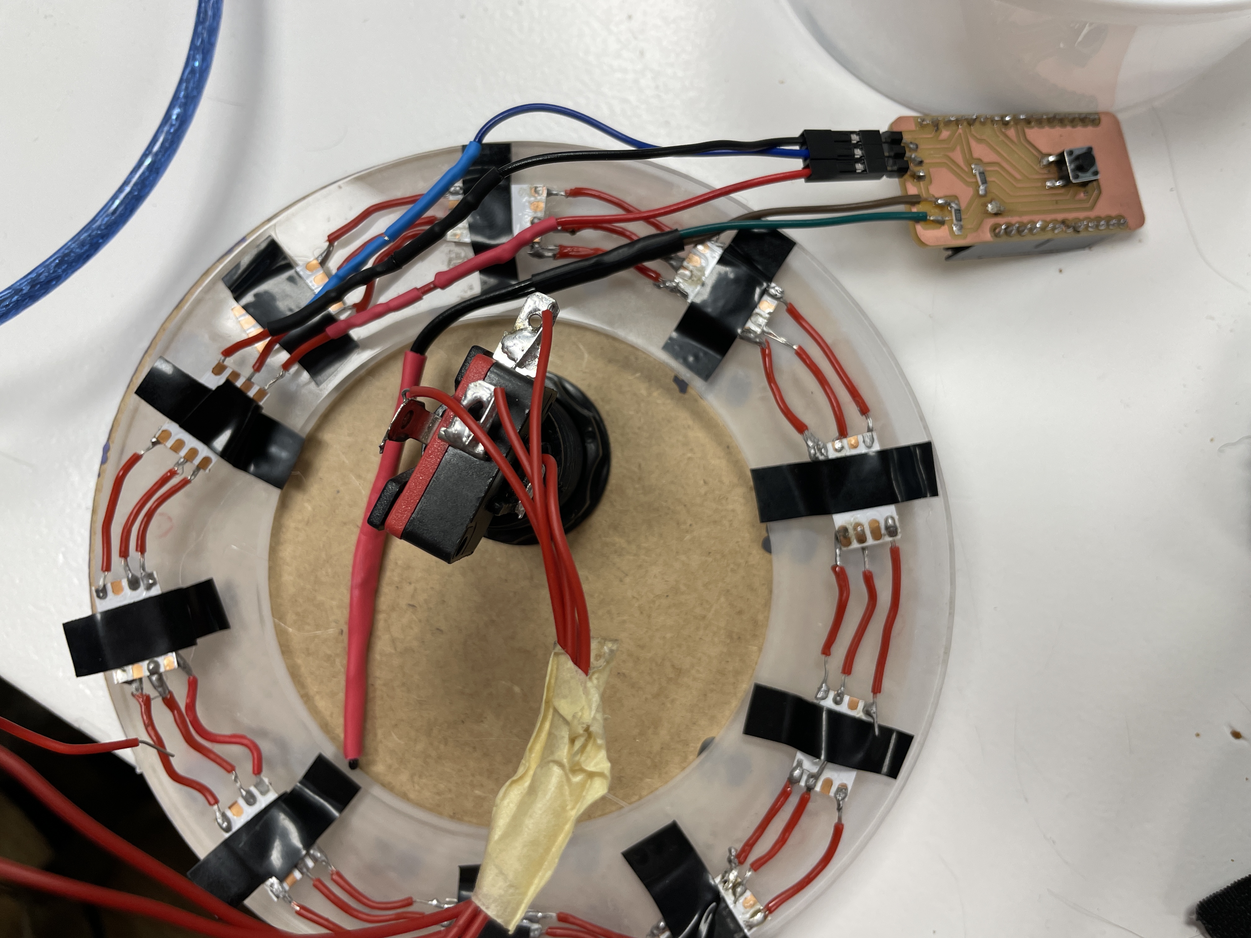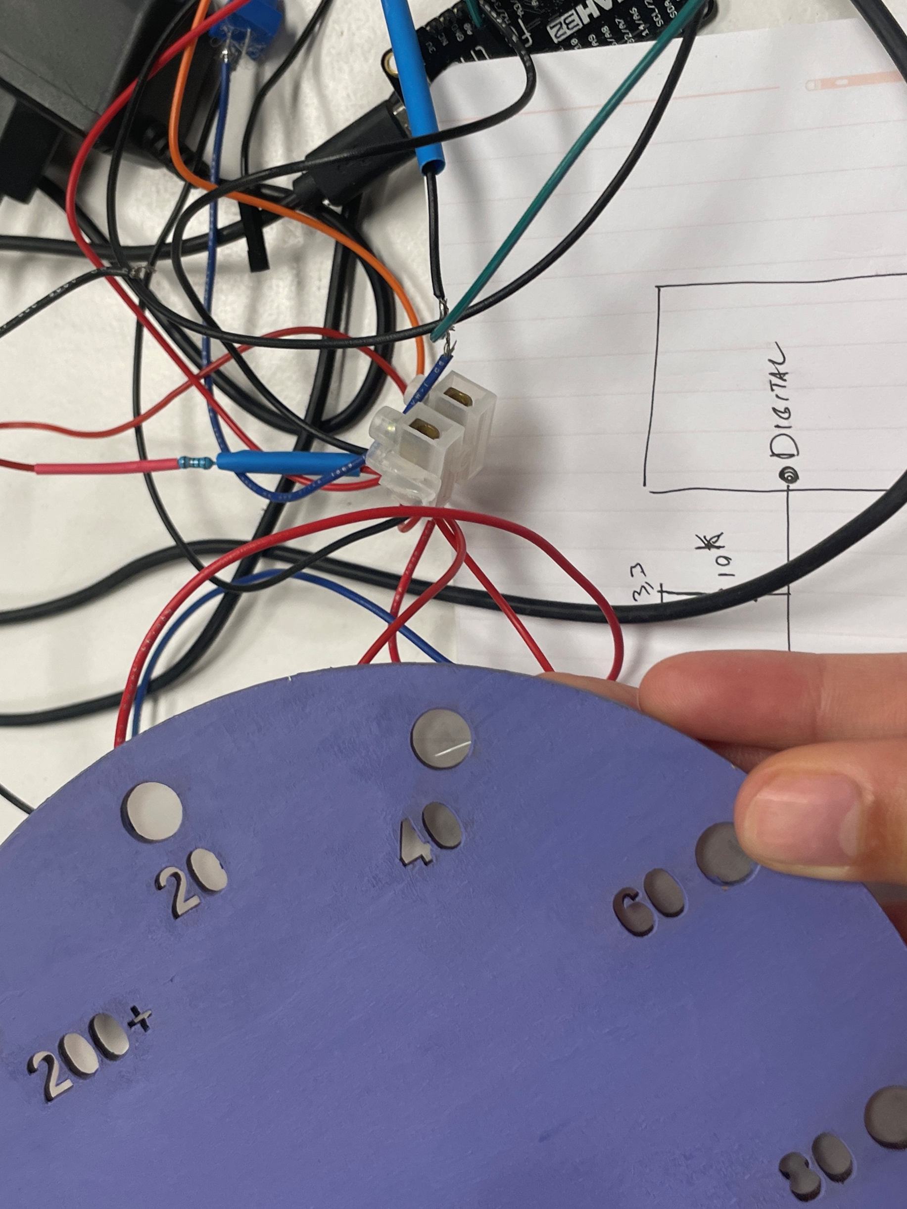
For this week of output devices I continued developing the pcb I designed and programmed it with the LEDs strip to work as our termometer. The termistor and button would be in this case the input and the LEDs the output. The LEDs are connected in a circular way so they can light up according to the round display we designed depending on which temperature the oven is in.
PROCESS.
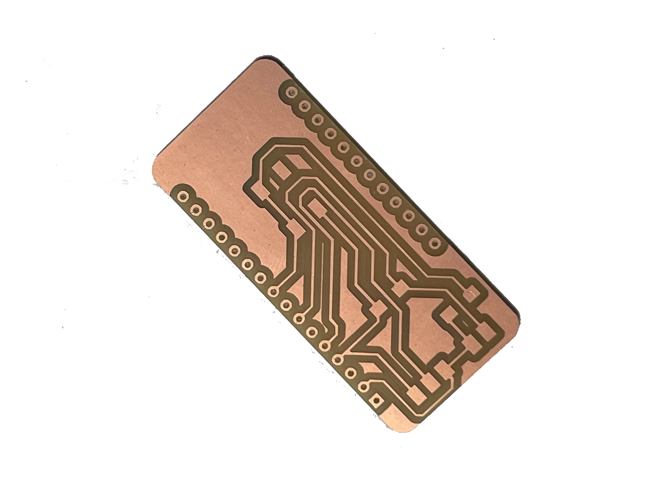
After exporting our files from the mods project website we went into the milling machine and selected a copper board and installed the bits. We started with the 1/64 bit to do the traces first. Setting the bit is tricky because the tip is very fragile and can break easily.
After inserting it you need to let it slide carefully until it touches the board. The board needs to be taped with double sided tape onto the mdf base so it stays in place. Once we have it touching the board then we set the Z as home. It is also important to set the XY to where you want to start the cut. We tried a technique to make sure the tip would go deep enough to mark the traces in which after setting Z you move up on the axis and activate the spinning and start going down until you see a bit of dust coming out meaning it's drilling into the board. We then loaded the file, first the traces, and sent the cut. After some cutting we realised it wasn't going all the way through.
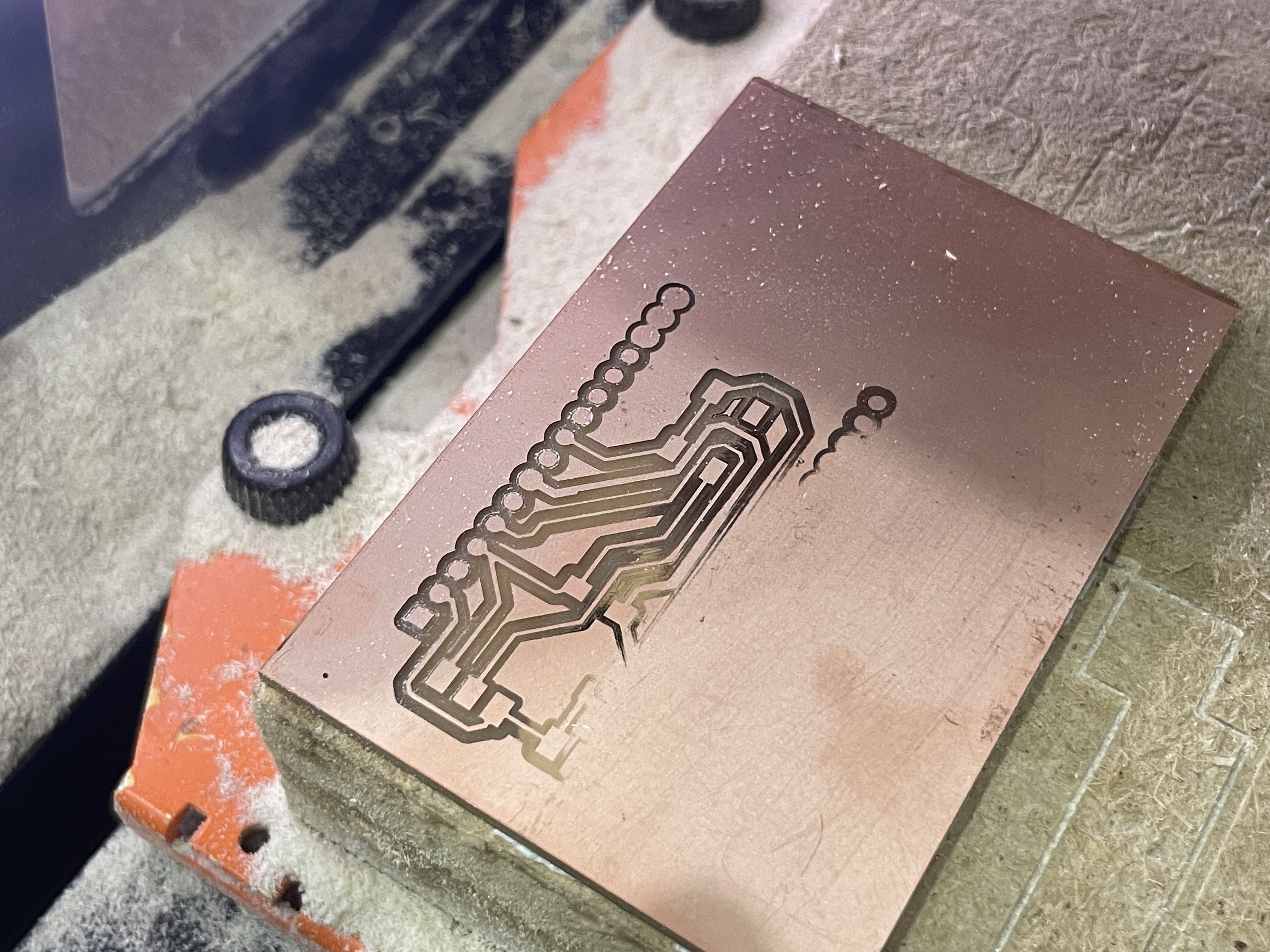
We could still see the shiny metal in it meaning it was still conductive on the side of the tracks. We had to take it out and put another one that was more flat. We reset the parameters again and started the cut. This time it was going deeper down. After doing the tracks we changed the bit to 1/32 and sent the drills and then the outline cut.
After the job was done we opened the machine, moved the Z up and remove the bit and then our board.
Now we can solder our components to our pcb.
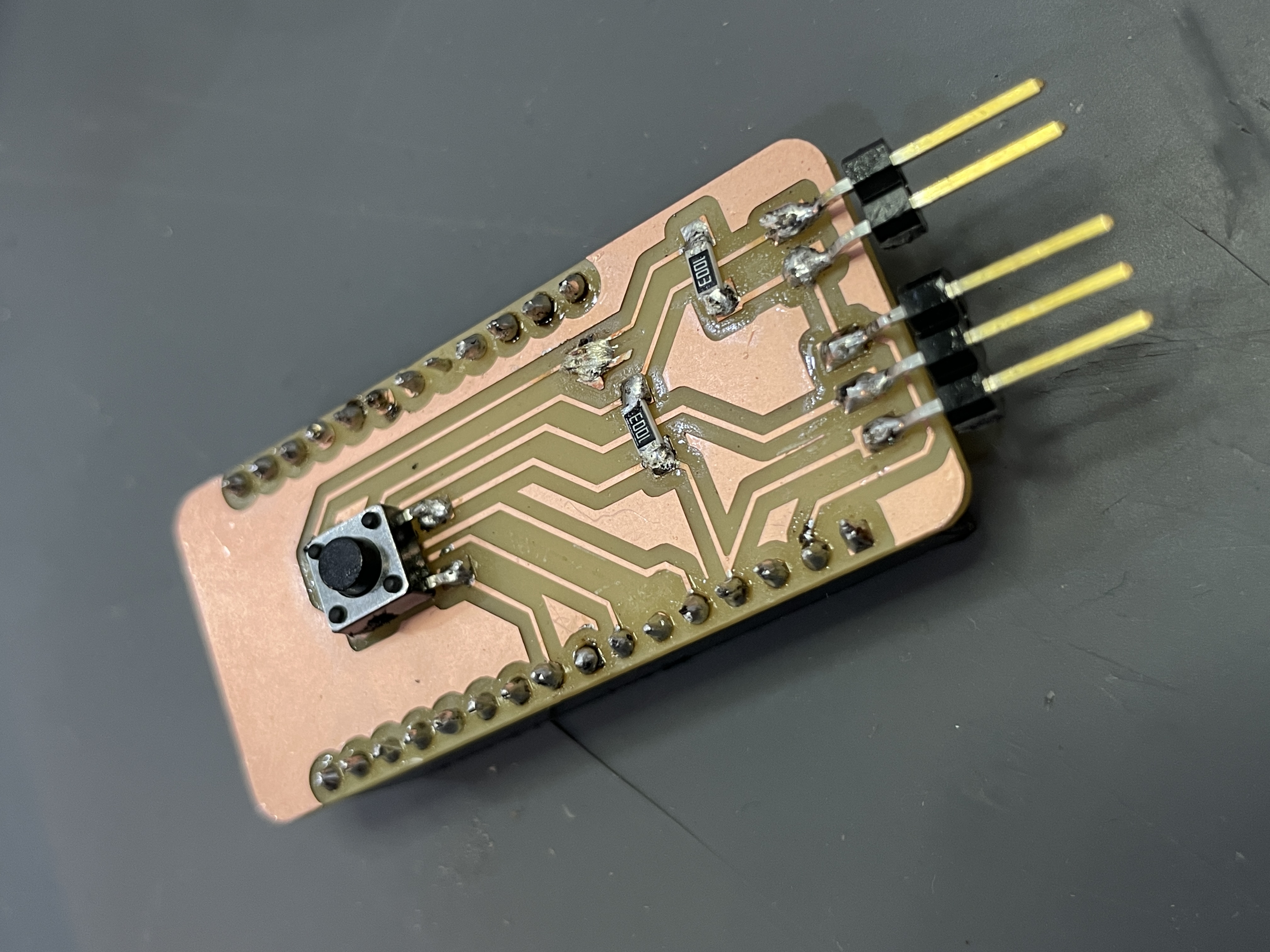
The input task will be part also of my pcb. As an input we have a button which will detect when to start collecting the data needed for the termometer. When the user places their food inside the solar oven and closes the door then they will press the button and start detecting the temperature level inside the oven. So after completing the milling of our pcb we were ready to start soldering the parts. We grabbed some pin headers to be able to connect the wires through there and some female pin headers in order to connect the esp32 to that and not solder it directly into the pcb. We realised our drills were slightly tight so we struggled a bit to pass the pins through but we used a clamp and managed to insert them. After we started soldering all the pins into the board and the resistors. While we were soldering we realised we added the space for a button but just not the button we were using so we used another smaller one.
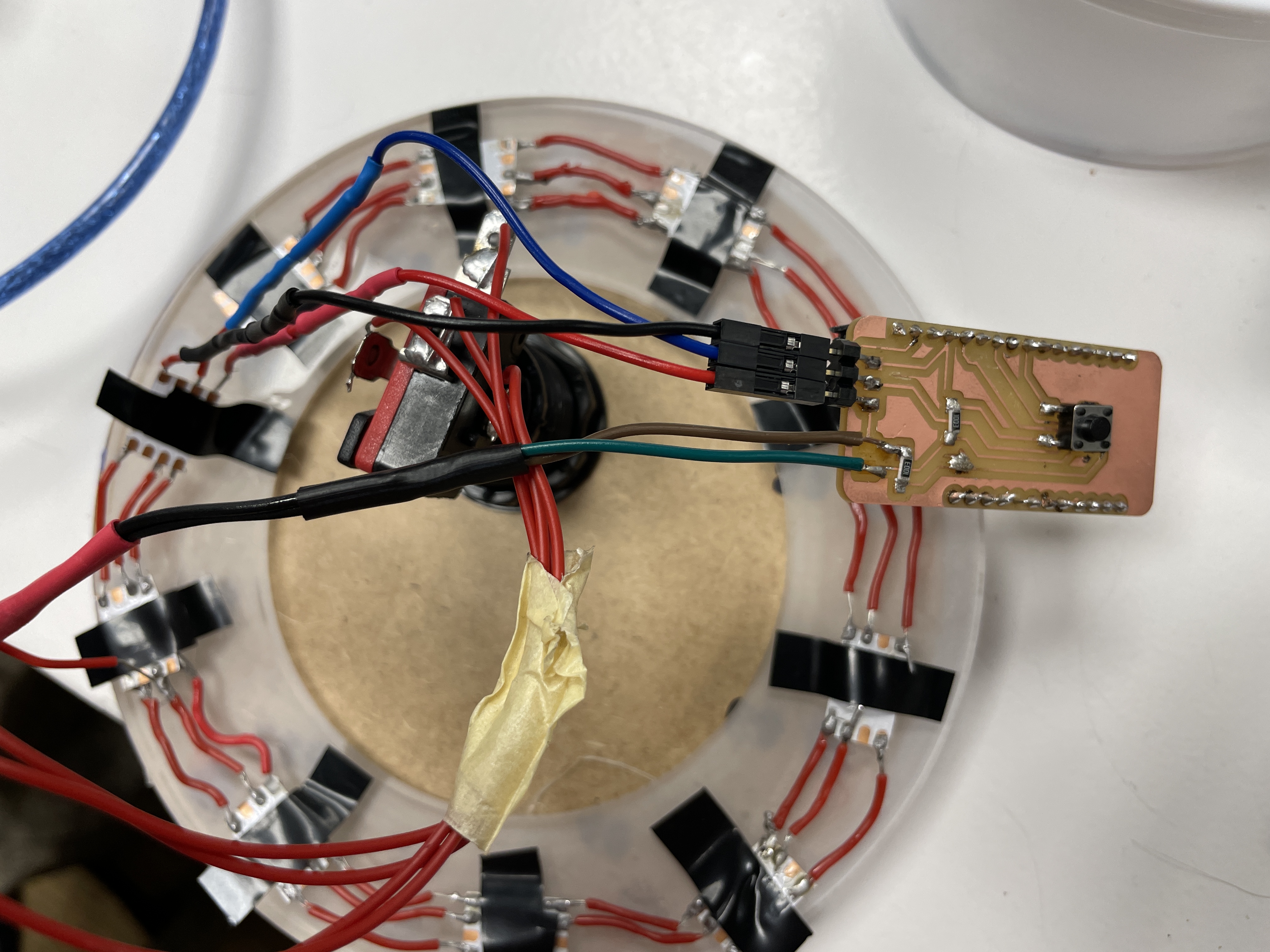
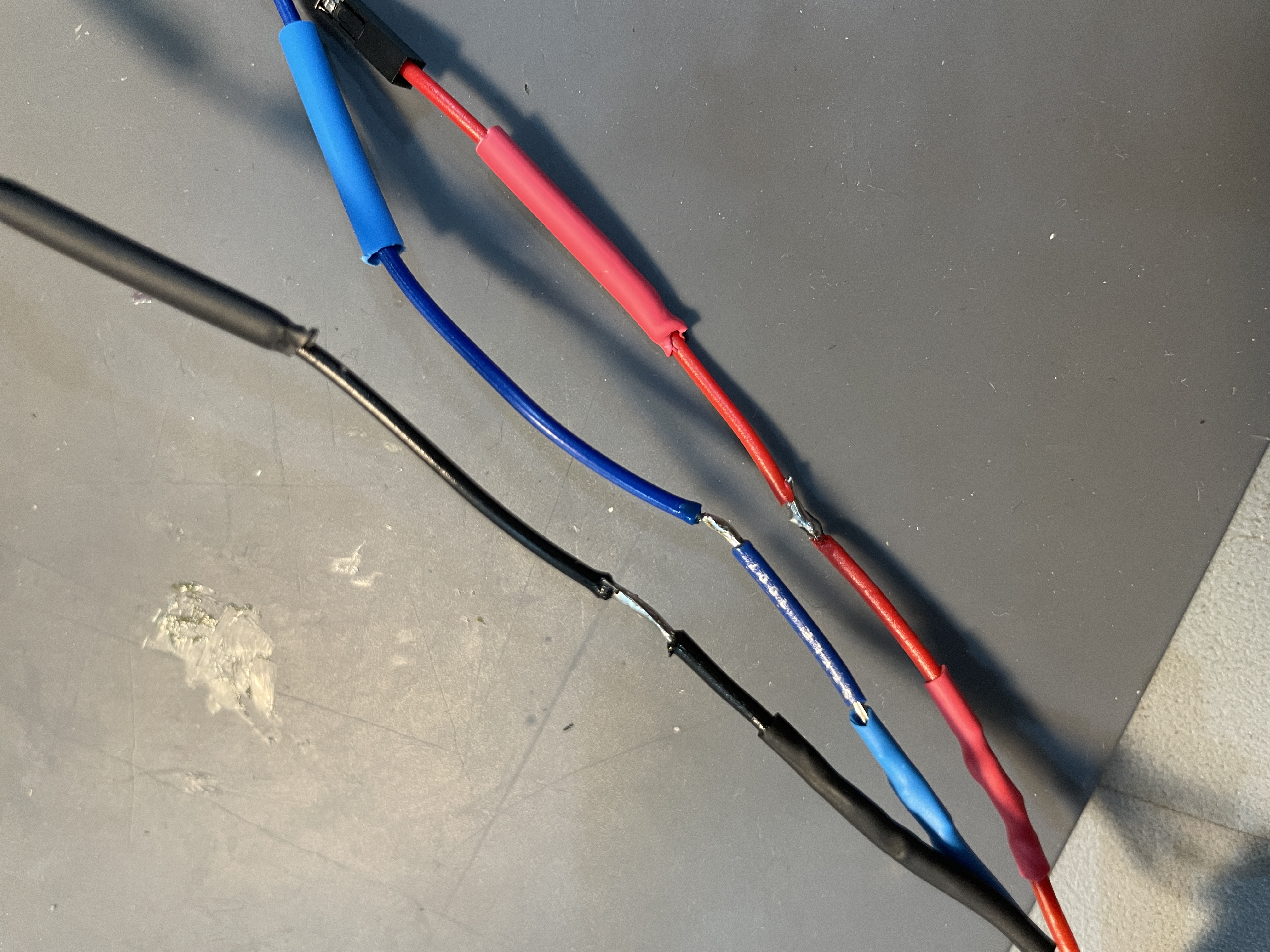
Now we will start wiring everything and replicate what we had but with the pcb. After soldering some components we got to know the soldering paste which is amazing. We tried it on the wired we had to solder between each other and the soldering was so sleek. You can see the difference in the next picture where black and blue were done with the paste.
While inserting the wires into the pin heads one of the pin headers broke apart from the pcb so we had to remove that part and solder the wires directly to the pcb. This is our result with the wiring now we just need to run it with the code to test if it works correctly.